|
I、Summarize
Based on the original stepping motor driver, we developed the 30822M type stepping motor driver. This driver owns many advantages such as low noise, high efficiency, low temperature rise, convenient settings, nice running characteristic and so on. | |
|
| |
Warning:Motor’s wires mustn’t be connected wrongly, Otherwise, the driver will be mangled.
Input signals
The inner interface circuit of the SH30822M are segregated by optically coupled isolators.
There are three connecting mode between the controller and the driver.
i. Differential
ii.Common-cathode
iii.Common-anode
Signal Amplitude |
R |
5V |
--- |
12V |
680Ω |
24V |
1.8KΩ |
DIR:Input port of the direction signal. High/low level
control the CW/CCW of motor. The changing
edge of the signal must be at least 2.5us later or
earlier than the falling edge of CP;
FREE: Free signal (active low). when this input end is
low level,there will be no holding torque of the
motor.
CP: Pulse signal input. active by the falling edge,the
highest response requency can be 200kHz,low
level pulse width should be not less than 2.5us。
RDY: A contact of the inner relay,just like a switch. It is ON when the driver is normal when the power turned on. It is OFF if the driver is abnormal.
Warning:Input signal must have enough current, (Currently, TTL, COMS signal are not drive firsthand). Otherwise, System can not run normally.
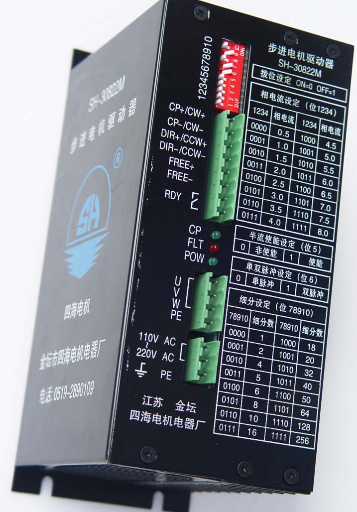
* phase current and subdivision number setting:
Shift switch is adopted to set phase current and subdivision number in SH30822M driver. There-into, Switch 5 is half phase-current (ON means full current , OFF means half), switch 6 is the setting of single or double pulse(ON show single pulse CP,DIR; OFF show double pulse CW,CCW). See Table2,Table3.After the subdivision of driver is set, the step angle in motor is equal to whole step angle divided by subdivision number. For example:if subdivision number is set to 18,its subdivision step angle is 1.8°/18=0.1°。
Warning:shift switch ON=0,OFF=1.
Phase current(bit 1 2 3 4) |
1 2 3 4 |
Value |
1 2 3 4 |
Value |
0 0 0 0 |
0.50A |
1 0 0 0 |
4.50A |
0 0 0 1 |
1.00A |
1 0 0 1 |
5.00A |
0 0 1 0 |
1.50A |
1 0 1 0 |
5.50A |
0 0 1 1 |
2.00A |
1 0 1 1 |
6.00A |
0 1 0 0 |
2.50A |
1 1 0 0 |
6.50A |
0 1 0 1 |
3.00A |
1 1 0 1 |
7.00A |
0 1 1 0 |
3.50A |
1 1 1 0 |
7.50A |
0 1 1 1 |
4.00A |
1 1 1 1 |
8.00A |
Table 2
subdivision(bit 7 8 9 10) |
78910 |
Number |
78910 |
Number |
0 0 0 0 |
1 |
1 0 0 0 |
18 |
0 0 0 1 |
2 |
1 0 0 1 |
20 |
0 0 1 0 |
4 |
1 0 1 0 |
32 |
0 0 1 1 |
5 |
1 0 1 1 |
40 |
0 1 0 0 |
6 |
1 1 0 0 |
50 |
0 1 0 1 |
8 |
1 1 0 1 |
64 |
0 1 1 0 |
10 |
1 1 1 0 |
128 |
0 1 1 1 |
16 |
1 1 1 1 |
256 |
Table 3
III、Installation Dimension:
 Disperse heat by compelling structure is adopted, so when installing, please keep enough space to elimination of heat when the driver installed (unit: mm) Disperse heat by compelling structure is adopted, so when installing, please keep enough space to elimination of heat when the driver installed (unit: mm)
|
|