Stepping Motor Basics
I. summarize
Stepping motors convert electrical energy into precise mechanical motion. These motors rotate a specific incremental distance per each step. The number of steps executed controls the degree of rotation of the motor’s shaft. This characteristic makes stepping motors excellent for positioning applications. For example, a 1.8° stepping motor executing 100 steps will rotate exactly 180° with some small amount of non-cumulative error. The speed of step execution controls the rate of motor rotation. A 1.8° stepping motor executing steps at a speed of 200 steps per second will rotate at exactly 1 revolution per second.
Stepping motors can be very accurately controlled in terms of how far and how fast they will rotate. The number of steps the motor executes is equal to the number of pulse commands it is given. A stepping motor will rotate a distance and at a rate that is proportional to the number and frequency of its pulse commands.
II.Principle of hybrid stepping motors
According to the principle of stepping motors , there are three types as Variable-reluctance, Permanent-magnet and hybrid. There-into, the hybrid stepping motors are most widely used. So to take the hybrid stepping motor for example, we will introduce the basic principle of stepping motors.
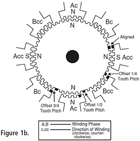
Figure 1a depicts a 1.8° hybrid step motor. The rotor contains a permanent magnet similar to those found in permanent magnet step motors. Hybrid rotors are axially magnetized, one end polarized north and the other polarized south. Both the rotor and the stator assemblies of hybrid motors have tooth-like projections. These “teeth” align in various configurations during rotation.
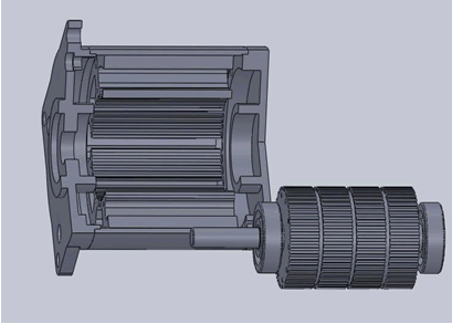
To understand the rotor’s interaction with the stator, examine the construction of a 1.8° (the most common resolution) hybrid stepping motor. First, the rotor is composed of two 50-tooth rotor cups enclosing a permanent magnet. The two cups are oriented so that the teeth of the top cup are offset to the teeth of the bottom cup by 3.6°. Second, the stator has a two-phase construction. The winding coils, 90° apart from one another, make up each phase. Each phase is wound so that the poles 180° apart are the same polarity, while the poles 90° apart are the opposite polarity. When the current in a phase is reversed, so is the polarity, meaning that any winding coil can be either a north pole or a south pole.
The driver controls this phase sequencing. Because there are 50 teeth on the rotor, the pitch between teeth is 7.2°. As the motor moves, some rotor teeth are in alignment with the stator teeth. The other rotor teeth are out of alignment with the stator teeth by 3/4, 1/2 or 1/4 of a tooth pitch. When the motor takes a step, it will move to the next closest position where the rotor and stator teeth are aligned. The rotor will move 1/4 of 7.2°. The motor will move 1.8° with each step.
Torque
When current is flowing through the windings , magnetic field will be generated between the rotor and the stator. When they offset some degrees, torque will be generated.

F is proportional to dΦ/dθ
magnetic flux Φ=Br*S
Br: magnetic density; S: area
F is proportional to L*D*Br
Static parameters
Phase: the numbers of the windings which generates different pairs of N-S polar.
Step : the number of pulses make the motor rotate a tooth. For examle the 2-phase 4-step motor and 4-phase 8-step motor. Step angle: the rotating angle is equal to a pulse(θ). θ=360°/the number of the teeth /the number of steps. For a 4-step motor with 50 teeth, θ=360°/50/4=1.8°. For a 8-step motor with 50 teeth, θ=360°/50/8 = 0.9°.
Detent torque: amount of torque that the motor produces when it is not energized. No current is flowing through the windings.
Holding torque: amount of torque that the motor produces when it has rated current flowing through the windings but the motor is at rest.
Dynamic parameters
i. Angle accuracy
Step Position Error: The maximum positive or negative position error caused when the motor rotated one step from the previous holding position.Step Position Error(%) = (the measured angle – the theoretical angle)/ the theoretical angle *100%. There are different values of different subdivisions. Take the SH2046D type stepping motor driver and 86BYG201 type stepping motor for example, the accuracy is ±5%.

Test condition : Motor: 86BYG201 , Driver: SH2046D , Voltage: 50VAc , Phase-current: 4A, subdivision: 2, full-current, unloaded.
Maximum error: 3.1%.

Test condition: Motor: 86BYG201, Driver: SH2046D, Voltage: 50VAc, Phase-current: 4A, subdivision :5, full-current, unloaded.
Maximum error: 12.8%.

Test condition: Motor: 86BYG201, Driver: SH2046D, Voltage: 50VAc, Phase-current: 4A, subdivision: 20, full-current, unloaded.
Maximum error: -21.4%.
Position Error
The motor rotates N steps from the initial position. The rotated angle is θ. The Position Error =θ- step angle *N. It is an important parameter of the motor. The value is repeat periodically. This period is one revolution.

Test condition: Motor: 86BYG201, Driver: SH2046D, Voltage: 50VAc, Phase-current: 4A, subdivision: 2, full-current, unloaded.
Maximum : 0.028°


Test condition: Motor: 86BYG201, Driver: SH2046D, Voltage: 50VAc, Phase-current: 4A, subdivision: 5, full-current, unloaded.
Maximum: 0.06°

Test condition: Motor: 86BYG201, Driver: SH2046D,Voltage: 50VAc, Phase-current: 4A, subdivision: 20, full-current, unloaded.
Maximum: 0.047°.
ii.Maximum Start Rate
The maximum starting step frequency with no load applied.
iii.Maximum Slew Rate
The maximum operating frequency of the motor with no load applied.
iv. Torque-Speed Characteristic
The torque vs speed characteristics are the key to selecting the right motor and drive method for a specific application. These characteristics are dependent upon the motor,excitation mode and type of driver method.
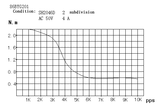
If the motor is certain, the holding torque is constant. But the dynamic torque is due to the average current of the windings. See the figure below, this is the same motor drived by three different drivers.
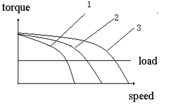
Curve 3 is drived by the biggest current or highest voltage, curve 1 is drived by the smallest current or lowest voltage. So if we want to get the better characteristic, we should make the voltage of the driver as high as possible.
v. Resonance
A step motor will exhibit much stronger vibrations when the input pulse frequency matches the natural frequency of the motor. This phenomenon is called resonance. In resonance, the overshooting and undershooting become much greater, and the chance of missing steps is much higher. The resonance range may change slightly due to the damping effect of the load’s inertia.
vi. Noise-Speed Characteristic
The characteristic describes the relationship between the noise and the running speed. It mostly depends on the character of the driver.

Test condition: Motor: 86BYG201, Driver: SH2046D, Voltage: 50VAc, Phase-current: 4A, Subdivision: 2, full-current, unloaded, surrounding noise 50dB
vii. Temperature Rise – Speed Characteristic
This characteristic is due to the drivers, especially in the low speed. And the temperature rise influences how many years the motor can be used for.

Test condition: Motor: 85BYGH201, Driver: SH2046D, Voltage: 50VAc, Phase-current: 4A,
Subdivision: 2, full-current,unloaded, surrounding temperature: 28℃
The influence of the driving voltage to the temperature rise.

How to choose stepping motors
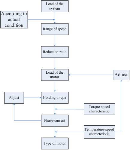
How to choose a stepping motor depends upon the three factors: step angle, holding torque, phase-current.
- Step Angle: The step angle depends on the requirer of the system. Converting the resolution of the sysmem to rotating angle of the motor. the step angle must be less than or equal to the rotating angle. This step angle is not just the step angle of the motor. It is equal to the step angle of the motor / the subdivision of the driver. For example, the step angle of the motor is 1.8°, and the max subdivision of the driver is 256, so the angle can be 1.8°/256=0.007°. Generally, a stepping motor with 1.8° step angle can be used for most systems.
- Holding Torque: The dynamic torque of the system may not be calculated immediately, so we can confirm the holding torque of motor. The holding torque deponds on the load of the motor when running. And there are two types of loads called inertial load and friction load. When the system started directly, this two types of loads must be calculated. If accelerating, the inertial load is mainly calculated. If constant speed, the friction load is mainly calculated. Generally, the holding torque of the motor is twice or three times of the friction load of the system. When the holding torque is certain, the dimension of the motor is also certain.
- Phase-current: the motors of same holding torque have different dynamic charateristics for the different phase-current. So we will select the right motor according to the torque-speed characteristic curve.
From these, choosing motors may accord to these steps.
Transfer relationship of torque and power
P=ω*M
ω=2πn/60
P=2πnM/60
The “ω” is angular velocity of the motor, “M” is the torque, “n” is the rotation speed per minute. |

